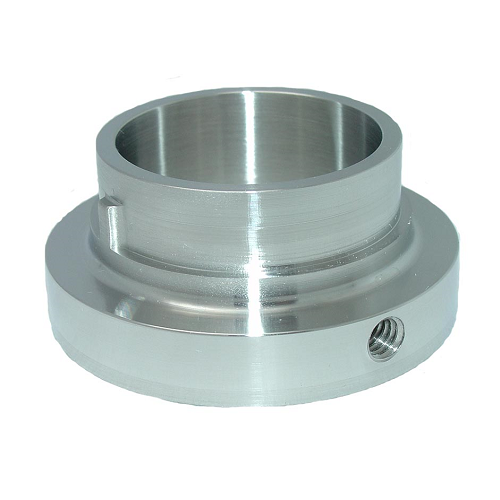
Drive Collar (MAR00)
- “D” / “E” Series Centrifugal Pump Drive Collar
- Available in sizes: 114, 216, 328
- Centrifugal Pump Manual
Replacement Centrifugal Pump Drive Collar
From time to time, centrifugal pump mechanical components need to be replaced. TOP-FLO® centrifugal pump replacement parts are specifically designed to fit in the pumps of not only TOP-FLO® pumps but those of major pump suppliers. These components are rugged and will provide the necessary sealing conditions under a wide range of conditions.
Drive Collar Adjustment
(Models TF-C114 through TF-C328)
- Slide the seal drive collar onto the stub
shaft as shown in Figure 24.
Use the “A” dimension in the SEAL CHART
to properly locate the drive collar on the
stub shaft. Tighten the set screws to
secure in place.
NOTE: TF-C100 pump does not require drive
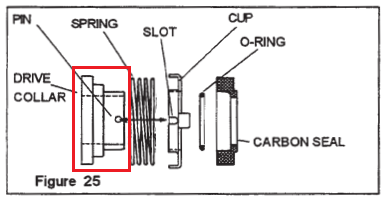
collar. - Assemble the spring, seal cup, o-ring, and
carbon seal, and install as a unit. Make
sure the slot in the seal cup aligns with
the pin on the shaft. (Figure 25) Gentle
pressure on the o-ring will overcome
resistance on the shaft.
NOTE: Do not lubricate seals with any
type of oil or grease, the seal faces will be
lubricated by the product being pumped. - Assemble the gasket to the backplate.
Install the backplate on the adapter. Make
sure the seal cup slot is engaged with the
pin on the drive collar. (Figure 25) - Rotate the backplate until the backplate
pins engage the adapter pins. (Figure 25) - Rotate the shaft until the pin hole in the
end is in a horizontal position. Insert the
impeller pin, center it in the shaft end, and
slide the impeller on the shaft.
Hold the impeller tight against the stub
shaft and rotate the shaft one-fourth turn
until the impeller pin drops and secures the
impeller. (Figure 26) - Place the casing over the impeller/
backplate, close and tighten the clamp.
(Figure 27) - Assemble the cascade water fitting, if
included. Install the seal guard and tighten
in place. Assemble the suction line and the
discharge line to the casing.
NOTE: Check for strain or misalignment
of piping to the casing. Re-adjust the
casing ports and/or entire motor leveling as
necessary.
Additional information
Line Drawings
| SKU | Description | Line Drawing |
|---|---|---|
| MAR00701S-316 | #80J 114E-23-316 E SEAL | Request Line Drawing |
| MAR00731S-304 | #80L SP114D-23P-316 DG SEAL | |
| MAR00736S-304 | #80L SP216D-23P-316 MILL | Request Line Drawing |
| MAR00711-316 | #80J 216E-23-316 MILL | Request Line Drawing |
| MAR00741S-304 | #80L SP328D-23P-316 MILL | Request Line Drawing |
| MAR00721 | #80J 328E-23-316 MILL | Request Line Drawing |
There are no questions yet. Be the first to ask a question about this product.