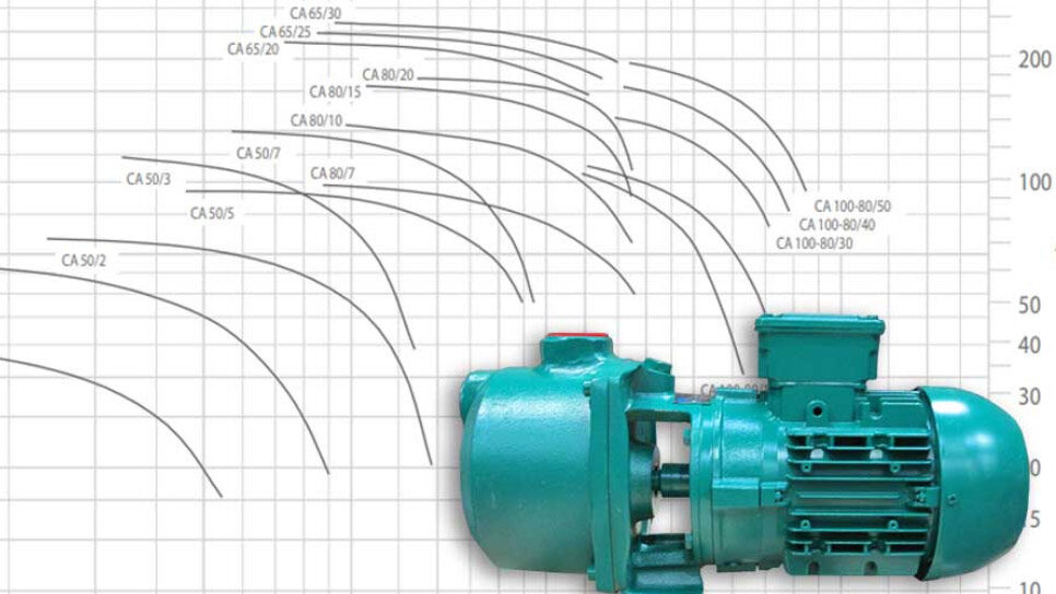
By understanding how to read pump curves, operators can make informed decisions regarding pump selection and operation.
This way, they can ensure maximum long-term performance. The wrong pump is more likely to operate inefficiently and fail prematurely.
Because a pump curve indicates how well a pump performs against specific rates of flow and pressure head, its proper interpretation will influence decisions regarding:
- Motor sizing: Associated with picking the correct motor for a given load
- Power consumption strategies: Lower horsepower translates to lower head pressure
- Pump selection: Associated with picking an appropriate pump for the application
- Pump efficiency: Extends pump life while reducing maintenance and operational costs
Remember, every pump is different, so pump curves vary in terms of type and model. For instance, the TOP-FLO® TF-C328 Centrifugal Pump can have four different capacity curves depending on certain factors shown in the table below.
| TF-C328 Centrifugal Pump | ||
| Revolutions Per Minute (RPM) | Port Size (In/Out) | Capacity Curve |
| 1750 | 4” X 2” | C328 4X2 1750 RPM Capacity Curve |
| 1750 | 3” X 2” | C328 3X2 1750 RPM Capacity Curve |
| 3500 | 4” X 2” | C328 4X2 3500 RPM Capacity Curve |
| 3500 | 3” X 2” | C328 3X2 3500 RPM Capacity Curve |
Reading a Pump Curve
Understanding how to read pump curves can be an invaluable resource that helps you make informed decisions when selecting and operating pumps.
For instance, pump operators who understand curves can ensure their pumps are working at maximum performance and efficiency for a given operation by:
- Determining the best impeller trim
- Using the correct pump speed or horsepower
- Calculating the ideal flow rate and head pressure
To read a pump curve correctly and make the most of it, operators need to understand the various components of the pump curve.
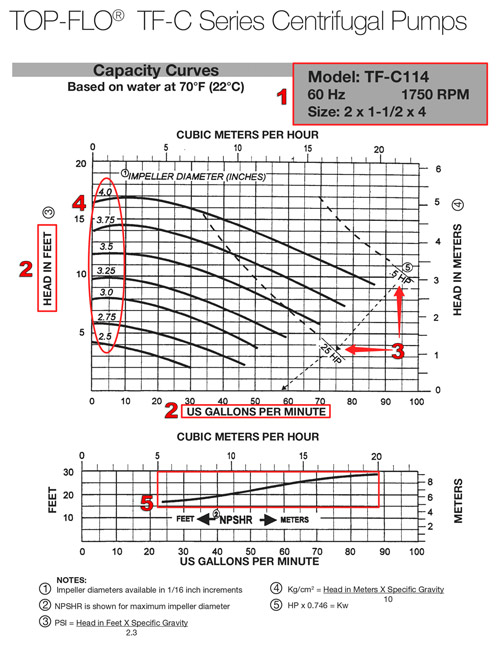
1 – Title Box
This box includes information about the pump, including its model, speed, size, and other identifying criteria. When checking the performance of an existing pump, ensure you’re matching it to the associated curve.
2 – Axis Labels
The pump curve has two axes, one for pressure and one for flow rate. Head pressure is usually plotted on the y-axis (vertical) and indicated in feet or meters of head.
Meanwhile, pump flow rate is plotted on the x-axis (horizontal) and usually indicated in gallons per minute (GPM).
3 – Horsepower
This is the pump’s horsepower, which indicates the pump’s power consumption and is usually indicated in HP. A dotted or serrated line across the curve, typically at a downward angle, indicates HP.
4 – Impeller Trim
Specific performance points can’t always be met with maximum impeller sizes. Therefore, centrifugal pumps accommodate varying performance points by allowing for trimmed impellers.
The different impeller trims (sizes) are listed on the curve line, and their performance is denoted by bold lines running from left to right.
5 – NPSHR
A pump’s Net Positive Suction Head Required (NPSHR) refers to the minimum pressure that must be maintained on the pump suction side for safe operation. Insufficient NPSHR will lead to cavitation, which negatively affects pump life and performance.
The pump curve does not identify NPSHA, the head pressure that a pump can actually deliver.
Using Pump Curves
Pump operators use curves to reveal a pump’s point of greatest efficiency for any given application.
For instance, using a pump curve can help one determine the horsepower or pump speed required to reach optimum flow rate and pressure. Indeed, a curve’s ability to show these details makes it an important consideration when pump sizing.
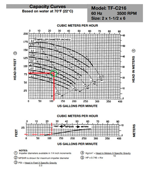
Now, there are several ways we can use a pump curve. Let’s take a TF-C216 Centrifugal Pump (whose graph is pictured above) as a case in point.
If the requirement is that we need to pump fluid at a flow rate of 110 GPM against total head pressure of 80’, we can determine:
1 – Duty Point
The duty point of our application is the intersection on the pump curve between the performance curve and the system characteristics.
Since this point is a combination of the head and flow rate for our application, we’ll follow these steps to determine it:
- Find the 80’ of head on the vertical axis.
- Trace the 80’ of head mark with a finger, ruler, or pencil to the right.
- Locate the 110 GPM on the horizontal axis.
- Trace the 110 GPM line with a finger, ruler, or pencil upwards.
The point at which the two lines (80’ of head line and 110 GPM line) intersect is the duty point of our application.
2 – Impeller Diameter
To determine the best impeller size to use for our application, we must first know where our duty point is.
Next, we check where the duty point falls in relation to the impeller curve lines. In this case, the duty point falls between the 4.75 and 4.5-inch impeller diameter.
Finally, always choose the impeller curve line that’s above the duty point, as it’s more efficient. Remember, the more the impeller is trimmed, the less efficient it is, mainly because of the larger clearances between it and the casing.
This means that the best impeller diameter choice for our application is 4.75 inches.
3 – Horsepower
To determine the ideal horsepower an application requires, we must once again start from the duty point.
Then, we check where the duty point lies in relation to the diagonal serrated lines that indicate motor horsepower (HP).
In this case, the duty point falls between the 3 and 5 HP lines, meaning that we require a 3–5 horsepower motor.
4 – NPSHR
Even when you’re aiming to move fluid at a flow rate of 110 GPM against a total head pressure of 80’, you can avoid pump issues like cavitation by ensuring the pump doesn’t operate below a certain minimum pressure.
A Net Positive Suction Head Required (NPSHR) graph can be very useful for determining this value:
- Start by plotting the intersection point of 110 GPM on the NPSHR graph.
- Follow the intersection point to the left to determine the corresponding value on the vertical axis.
- That value (it’s in feet in this case) is the NPSHR.
In our case, the NPSHR is 5 feet.
Remember: The NPSHA, which is the absolute pressure acting on a fluid as it enters the pump, must be greater or equal to NPSHR to prevent pump cavitation.
Get the Most Out of Pump Curves
Pump curves are a valuable tool for pump operators. By understanding how to read and use pump curves, pump operators can make informed selection and operation decisions.
Following these expert tips will ensure pump operators get the most out of pump curves:
- Before selecting a pump, compare the curves of various pumps. This will help operators determine which pump is best for their application.
- Investigate pump curves at different impeller sizes and pump speeds to determine optimal performance.
- Use pump curves to set the pump speed for optimal performance.
- Monitor pump operation using pump curves to ensure efficient operation.
If you’re still not too sure how to read and use pump curves, it’s an excellent idea to consult reliable pump experts before buying a pump.
But even if you’re a pro, the team at Sanitary Fittings will quickly and helpfully point you in the right direction. This way, you’ll always come out on top when it comes to choosing from the best sanitary pumps for your application.
Sanitary Fittings doesn’t skimp on product quality or customer service, as Rob Mozur discovered:
“Dealing with Sanitary Fittings was a joy. The website was easy and straightforward to navigate. Brad answered my questions with a high degree of knowledge and professionalism. Thank you and keep up the great work!”
Share on LinkedIn:

